Street Source is shutting down April 30th, 2026. Read the announcement
L
Air Ride Switch Wiring
J
jibee
+1y
I am trying to figure out how to wire my switches up for my air ride setup. I have found 3 pin momentary and 6 pin momentary switches. I am confused on how what wires go from where to where and such. I will probably be mounting them in either my console or in one of the dash bezels up around the steering wheel. Im running an 8 valve setup but I only really want a switch for front, back, driver front, passenger front, driver rear, and passenger rear. So in total I need 6 switches. But I am totally lost on how to wire this stuff up. I am sure somebody can help me out. Diagrams or any kind of illustrations would be great.

dragginmazda86 (dave)
+1y
Thats pretty much the same switch config Im running. 6 switches, 2-6 prong for front and rear and 4-3 prong for individual corners. When I get home I'll post a couple pics and help you with the wiring.
J
jibee
+1y
That would be great. Im confused on what wire goes where with a 6 prong. Its just kind of feeling overwhelming but I want to get this figured out.

paparoach1983
+1y
Yes i would also like to know this as well.
dragginmazda86 (dave)
+1y
I snapped a couple pics. I will upload them and write a description when I get home from work.
dragginmazda86 (dave)
+1y
I snapped a couple pics. I will upload them and write a description when I get home from work.
dragginmazda86 (dave)
+1y
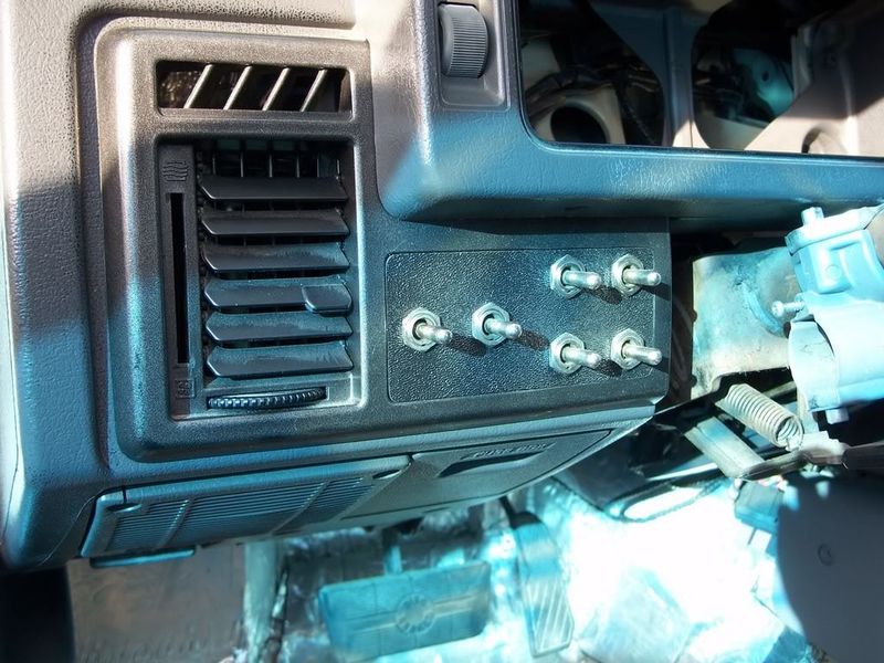
Heres how my switches are mounted. The far left switch controls front valves, the switch right next to controls the rear valves. As for the next four switches, upper left controls LF valves, upper right controls RF valves, lower left controls LR valves, and lower right controls RR valves.
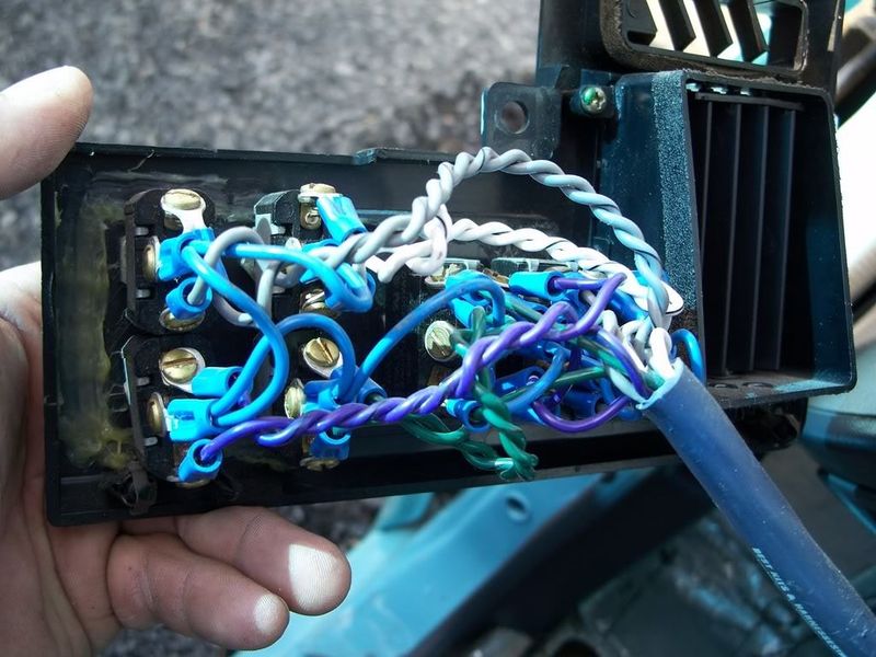
Heres a pic of the back side:
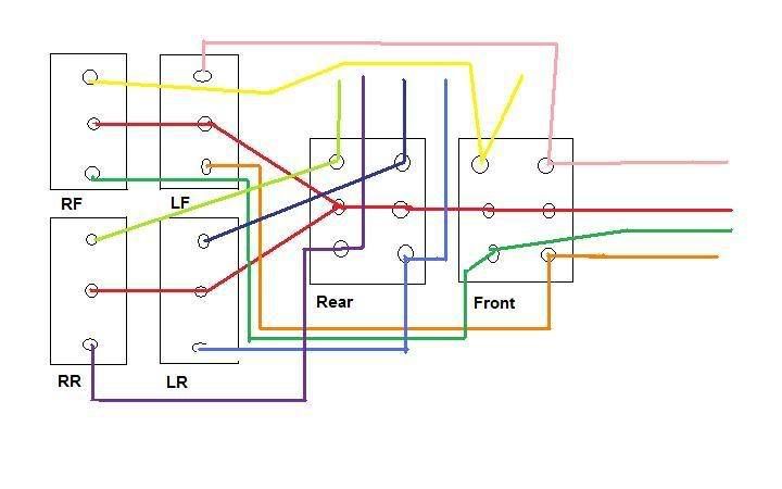
Now heres a crude MS paint diagram of how my switches are wired. The diagram is as if you were lookin at the back side of the switches.
Red= 12 volts input
Pink= LF down valve
Orange= LF up valve
Yellow= RF down valve
Dark Green= RF up valve
Dark Blue= LR down valve
Medium Blue= LR up valve
Lime Green= RR down valve
Purple= RR up valve
Heres a pic of the back side:
Now heres a crude MS paint diagram of how my switches are wired. The diagram is as if you were lookin at the back side of the switches.
Red= 12 volts input
Pink= LF down valve
Orange= LF up valve
Yellow= RF down valve
Dark Green= RF up valve
Dark Blue= LR down valve
Medium Blue= LR up valve
Lime Green= RR down valve
Purple= RR up valve
dragginmazda86 (dave)
+1y
Hope this helps you guys out. If you have any questions I'll try my best to answer them.
J
jibee
+1y
Thats a clean install and exactly where and how I am planning on doing my switches. What size wire did you use? I am thinking of using these switches but they are all 6 prong. how would that effect the diagram if any?
Great pics and great diagram.
Great pics and great diagram.
dragginmazda86 (dave)
+1y
I used 16 gauge wire. If you really want to run those switches in your link, for the individual corner switches you would just use the three prongs on one side but I recommend that you put some heat shrink on the bare prongs on the other side just in case because they will be "hot".


