Street Source is shutting down April 30th, 2026. Read the announcement
Mitsubishi Mighty Max build. hydroholics, all day!
26153 views
413 replies
136 following

Mitsubishi Mighty Max build. hydroholics, all day!

tre5
+1y
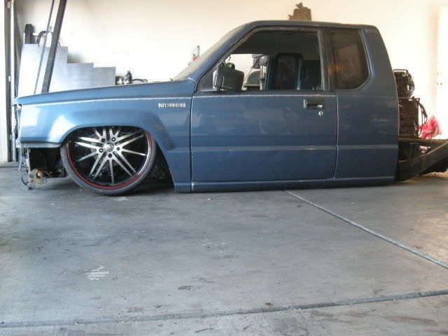
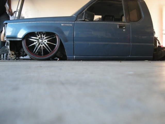
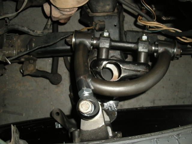
Well we got the truck back down on the ground. It is now laying flat. The new upper and lower control arms are in also. 1 1/4" tubular (chromoly) upper arms with 3/4" heims. I had to machine down the stock cross shafts to fit the bushing sleeves. The lowers are mainly plate, but the strut rod is the same tube as the uppers with a bushing pivot. I will take better pictures of them later. The arms narrow the suspension 1" on each side. The camber is at 0 degrees when all the way up, which is untucking the tire by about 1 1/2". When the truck is all the way down there is 4 degrees of negative camber. So I would say the arms came out just the way I wanted.

20runner
+1y
Uppers look AWESOME!!!!!!!!!!!!!!!

FluffyFreak
+1y
like the uppers man! effin sick!

smctoy
+1y
wow!!

solowkustomz06
+1y
what did you guys do about the power steering problem?

railin93
+1y
got a small question...is the upper uni-ball in the same location as the factory balljoint?...i love the tube design of the uppers and the way you used the one tube for a good, sold mount instead of putting the uni-ball in a joint...awesome work...oughta think about building those if they work as good as you say they do!...

k24 rd6
+1y
Damm Jeremy, I didn't realize your tig welding was so good. Those arms look great.
tre5
+1y
---------------------------------------------Originally posted by SLKYOTAwhat did you guys do about the power steering problem?
---------------------------------------------The "power" of the steering wasn't the problem. The problem with the steering on these trucks is that the box is right up against the firewall. They are a rear steer truck. We wanted to trim the bottom of the engine crossmember down and not Z the frame. That way the box was only the 2" higher with the body drop. The problem there was that the drag link hangs almost as low as the crossmember. So that would have been on the ground and holding the truck's frame off the ground. We looked at putting a rack and pinion in it. We tried one out of a car, but it didn't work. We would have had to do a bunch of R&D to find one that fit right. We ended up just Z'ing the frame 1-1/4". Now there is just the issue with the steering column. We are going to have to cut the steering column inside the truck and use some joints to get everything lined up again.
tre5
+1y
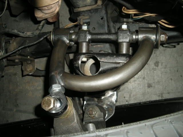
---------------------------------------------Originally posted by railin93got a small question...is the upper uni-ball in the same location as the factory balljoint?...i love the tube design of the uppers and the way you used the one tube for a good, sold mount instead of putting the uni-ball in a joint...awesome work...oughta think about building those if they work as good as you say they do!...---------------------------------------------The arms I made narrow the track width 1". The lowers are actually 1" narrower. The upper arms are exactly the same length as stock. If you notice in the pics, the upper is spaced back 1" on the crosshaft. The thought was it would make the arms closer to the same length which usually gets rid of some camber change. It took me 3 attemps on the uppers. The lower I only built once, but had to modify the ball joint angle on them to get the travel out of them. I thought about making them for sale, but there really isn't a market for them... how many of these do you see? Plus, they are expensive to build, so they would have to be more to sell.
tre5
+1y
---------------------------------------------Originally posted by k24 rd6Damm Jeremy, I didn't realize your tig welding was so good. Those arms look great.
---------------------------------------------yeah... I can't tig worth a shit.
Related Discussions in Build-Ups
Thread
Posts
Last Post
32

last post by
baha 5 mo
0
V
last post by
Vic 9 mo

168

last post by
truck action +1y