Street Source is shutting down April 30th, 2026. Read the announcement
Relay wiring and such- HELP
1339 views
14 replies
5 following
Relay wiring and such- HELP

baggedK
+1y
Ok... I think I have this figured out- but can someone double check me and tell me if this is right.
What I am doing is running a reverse polarity power window motor off two SPST pushbutton momentary switches. These having one in and one out- pos-constant in pos-switched out. This is a hommade (BY ME) diagram on paint that shows what I have planned to wire.
Instead of using a standard 5-pole power window switch which reverses polarity itself, I'm hoping this will do the same job all-together. I am also using an Autoloc 16channel remote system which will work the windows, the diagram shows this as well.
Someone has to be able to help out!

dssur
+1y
your way will work, but that is pretty complicated.
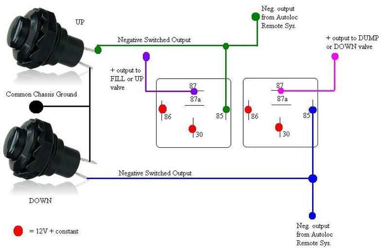
You can do it with just two relays if you make your switches ground triggers instead of 12v. then you switch 85 to 12v+ (do not tie it to 87a any longer) 30 is out to the window motor (no need for the second relay) and you attach both the switch and the auto loc - trigger to 86.
I'll work on a picture.
dssur
+1y
Here is what I was talking about
baggedK
+1y
The window motor wires have to be a ground at rest and positive when triggered in order to operate in up/down motion.
I'm not following the statement "(do not tie it to 87a any longer)".
I'm not following the statement "(do not tie it to 87a any longer)".
baggedK
+1y
Hmm ok that helps visualize it alot......
baggedK
+1y
I've always been told I like to overcomplicate things..... proof once-again... hope this works out as easy as it looks. Thanks.
baggedK
+1y
I've always been told I like to overcomplicate things..... proof once-again... hope this works out as easy as it looks. Thanks.
Two more questions for ya Russ.....
1.) What is the equation to figure 125VAC Amps to 12VDC Amps. For example if a switch is rated 3A 125VAC what is it's A capability at 12VDC. Same with 10A 125VAC, what would the 12VDC A rating be?
2.) Would it hurt the 1/2" Valve solenoid coil if both sides were grounded and then the one-side triggered positive (exact same setup as the power window switches/relays setup?... or would I need to wire those differently from the switches to the airride valves including the autoloc remote system?
dssur
+1y
Originally posted by baggedK
I've always been told I like to overcomplicate things..... proof once-again... hope this works out as easy as it looks. Thanks.
Two more questions for ya Russ.....
1.) What is the equation to figure 125VAC Amps to 12VDC Amps. For example if a switch is rated 3A 125VAC what is it's A capability at 12VDC. Same with 10A 125VAC, what would the 12VDC A rating be?
2.) Would it hurt the 1/2" Valve solenoid coil if both sides were grounded and then the one-side triggered positive (exact same setup as the power window switches/relays setup?... or would I need to wire those differently from the switches to the airride valves including the autoloc remote system?
for the switches, an AC rating will translate to a slightly higher rating dc. They dont make many high amperage ac switches though( and if they do they are usually multi gang to split the load, I have some 15a 120v switches that are three gang)
2. it depends on your current switch set up. If you aren't using a multi switch box and just have basic up/down, you could use a positive trigger on the up switch, and another on the down ( I am assuming you want lift/lower with the remote?)
If you ARE using a multi switch box, you will wire each valve like a window switch (8 valves = 8 relays needed) BUT do NOT ground 87a. Instead, cut the wire from the switchbox that goes to that valve, and put the SWITCHBOX side of the cut wire on 87a, and the VALVE side of the cut wire on 30.
85 and 86 are your relay coil, its really just an electromagnetic switch, so if you have a - trigger from the autoloc, use that on either one (85 or 86) and put the opposite on the other (12v + in this case)
87 is what you want tranferred, in the case of your valve it will be 12+.
You can NOT just ground both sides of the valve, it is not a two way motor like a window motor is. The window motor is reversing because of that reversing polarity, you put 12+ on the first wire and ground on the second and it spins clockwise. You put 12v+ on the second wire and ground on the first and it will spin COUNTER clockwise. A valve solenoid is spring loaded, it returnes to NC when power is taken away, so there is no need to reverse polarity.
Sorry for the book, but I hope it helped!
baggedK
+1y
The airride switches are the exact same 3A 125VAC momentary switches I am using (as pictured in my diagram) for the windows. I will have front/back only- I'm not into the side/side hop, skip, fart, dance BS that everyone else may be into.
Yes the airride valves will be wired into the autoloc 16channel remote system that has .500ma neg triggers. I was just wondering if it would be as-easy to run these same switches negative as well just like the windows if it would hurt the coil if both sides were grounded normally and switched positive when triggered.
Now that I understand how the coil works, I guess I will be wiring them up just like the relays are wired on the door solenoids.
baggedK
+1y
Here- check this diagram and tell me if it would work.....
Related Discussions in Mini Truckin General
Thread
Posts
Last Post