Street Source is shutting down April 30th, 2026. Read the announcement
HEADLIGHT WIRING UPGRADE - CUSTOM HARNESS - PICS UP ENJOY
Last Updated: Feb 24, 2015
So the first thing you need to do is figure out what you are going to do with your lighting, are you going to run high power bulbs down the road, or do you just want a bit of an improvement for everyday driving.
It makes a difference as to which products you use.
Now get a multimeter, Pen and Paper and do the following.
Turn the Multimeter onto DC 20 volts( some may be different but you need at least 16 volt capability to measure this )
start your truck, turn off the stereo and all accessories, and turn on the headlights. Let the truck idle for a minute or so.
Now measure and write down your battery voltage, it should be around 13.8 - 14.4, if not you might also consider getting you battery tested, and or your alternator tested to make sure they are in good working order.
Now take the black(-) lead of your multimeter and place it on the posotive battery terminal, and take the red(+) lead and touch it to the LO beam headlight on the drivers side. It should not read 0 and it should not be anywhere near Battery voltage. Most of the time it will be around 1.5 - 2.5 volts. Write this down, this is the (+) voltage drop for the drivers low beam. Now do the same for the passenger low beam, again write this number down, and then do the high beams (obviously you will need to turn the lights from lo to high beam for this part of the test ) on both sides and write these numbers down. You should have 4 numbers written down. Now take the (-) black lead on your multimeter and touch it to the negative battery terminal and test the ground on both headlights ( again you will need to switch between lo and high beam and write these numbers down.
Heres the fun part, you need to be able to add for this one...LOL
take the (-) and (+) from each beam passenger hi, passenger lo, drivers hi, drivers lo, and add them together, you should now have 4 numbers. These represent the total voltage loss at each beam.
Now figure that the LUMENS, or light output of the bulb will be directly affected by the input voltage of the bulb and you will see why a 2 - 4 volt drop is very significant.
10.5V : 510 lumens
11.0V : 597 lumens
11.5V : 695 lumens
12.0V : 803 lumens
12.5V : 923 lumens
12.8V : 1000 lumens ←Rated output voltage
13.0V : 1054 lumens
13.5V : 1198 lumens
14.0V : 1356 lumens ←Rated life voltage
14.5V : 1528 lumens
( the above is from DS lighting)
Credits
Created By: gravity5
Related Articles
1992 b2600i 4x4. Chevy 17 wheel custom fit center hubs
I could not find a write up on anyone doing a Chevy wheel swap onto a 4x4 so here it is. Wheels are...
How to: custom shifter boot
I thought i would make a thread about the shifter boot i made but although its really easy i wanted ...
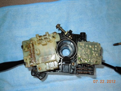
Combination Switch Or Headlight Switch Exposed!
OK........I did a little write up over at MT on the Headlight Switch (HLS) that seems to go bad on o...
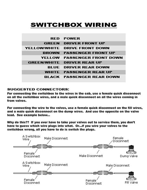
How To: Switchbox Wiring
[pid]17919[/pid]