Street Source is shutting down April 30th, 2026. Read the announcement
Carb repair & rebuild manual
Last Updated: Feb 24, 2015
Heres some info I ran across while researching a fix for my carb. This is pretty detailed and in depth. I decided to rebuild my carb and this is the best write up I've found to do it with. The diagrams are hosted on my photobucket account right now. If someone has a more permanent host let me know. I'd hate for the pics to go down in the future and no one be able to see them anymore. Clicking on the pics will bring up a slightly larger pic with better detail.
REMOVAL & INSTALLATION
1. Remove the air cleaner and duct.
2. Disconnect the accelerator shaft from the throttle lever.
3. Disconnect and plug the fuel supply and return lines.
4. Disconnect the leads from the throttle solenoid and deceleration valve at the quick-disconnects.
5. Disconnect the carburetor-to-distributor vacuum line.
6. Disconnect the throttle return spring.
7. Disconnect the choke cable, and, if equipped, the cruise control cable.
8. Remove the carburetor attaching nuts from the intake manifold studs and remove the carburetor. The attaching nuts are tucked underneath the carburetor body and are difficult to reach; a small socket with an L shaped hex drive, or a short, thin wrench sold for work on ignition systems will make removal easier.
To install:
9. Install a new carburetor gasket on the manifold.
10. Install the carburetor and tighten the carburetor attaching nuts.
11. Connect the throttle return spring.
12. Connect the accelerator shaft to the throttle shaft.
13. Connect the electrical leads to the throttle solenoid and deceleration valve.
14. Connect the distributor vacuum line.
15. Connect the fuel supply and fuel return lines.
16. Connect and adjust the choke cable and, if equipped, the cruise control cable.
17. Install the air cleaner and duct.
18. Start the engine and check for fuel leaks.
OVERHAUL
The following instructions are general overhaul procedures. Most good carburetor rebuilding kits come complete with exploded views and specific instructions.
Efficient operation depends greatly on careful cleaning and inspection during overhaul, since dirt, gum, water, or varnish in or on the carburetor parts are often responsible for poor performance.
Overhaul your carburetor in a clean, dust-free area. Carefully disassemble the carburetor, referring often to the exploded views. Keep all similar and look alike parts segregated during disassembly and cleaning to avoid accidental interchange during assembly. Make a note of all jet sizes.
When the carburetor is disassembled, wash all parts (except diaphragms, electric choke units, pump plunger, and any other plastic, leather, fiber or rubber parts) in clean carburetor solvent. Do not leave parts in the solvent any longer than is necessary to sufficiently loosen the deposits. Excessive cleaning may remove the special finish from the float bowl and choke valve bodies, leaving these parts unfit for service.
Rinse all parts in clean solvent and blow them dry with compressed air or allow them to air dry. Wipe clean all cork, plastic, leather, and fiber parts with a clean, lint-free cloth.
Blow out all passages and jets with compressed air and be sure that there are no restrictions or blockages. Never use wire or similar tools to clean jets, fuel passages, or air bleeds. Clean all jets and valves separately to avoid accidental interchange.
Check all parts for wear or damage. If wear or damage is found, replace the defective parts. Especially check the following:
1. Check the float needle and seat for wear. If wear is found, replace the complete assembly.
2. Check the float hinge pin for wear and the float(s) for dents or distortion. Replace the float if fuel has leaked into it.
3. Check the throttle and choke shaft bores for wear or an out-of-round condition. Damage or wear to the throttle arm, shaft, or shaft bore will often require replacement of the throttle body. These parts require a close tolerance of fit; wear may allow air leakage, which could affect starting and idling.
Throttle shafts and bushings are not included in overhaul kits. They can be purchased separately.
4. Inspect the idle moisture adjusting needles for burrs or grooves. Any such condition requires replacement of the needle, since you will not be able to obtain a satisfactory idle.
5. Test the accelerator pump check valves. They should pass air one way but not the other. Test for proper seating by blowing and sucking on the valve. Replace the valve if necessary. If the valve is satisfactory, wash the valve again to remove breath moisture.
6. Check the bowl cover for warped surfaces with a straight edge.
7. Closely inspect the valves and seats for wear or damage, replacing as necessary.
8. After the carburetor is assembled, check the choke valve for freedom of operation.
Carburetor overhaul kits are recommended for each overhaul. These kits contain all gaskets and new parts to replace those that deteriorate most rapidly. Failure to replace all parts supplied with the kit (especially gaskets) can result in poor performance later.
Some carburetor manufacturers supply overhaul kits of three basic types: minor repair; major repair; and gasket kits. Basically, they contain the following:
Minor Repair Kits:
• All gaskets
• Float needle valve
• Volume control screw
• All diaphragms
• Spring for the pump diaphragm
Major Repair Kits:
• All jet and gaskets
• All diaphragms
• Float needle valve
• Volume control screw
• Pump ball valve
• Main jet carrier
• Float
• Complete intermediate rod
• Intermediate pump lever
• Complete injector tube
• Some cover hold-down screws and washers
Gasket Kits:
• All gaskets
After cleaning and checking all components, reassemble the carburetor, using new parts and referring to the exploded view. When reassembling, make sure that all screws and jets are tight in their seats, but do not overtighten as the tips will be distorted. Tighten all screws gradually, in rotation. Do not tighten needle valves into their seats; uneven jetting will result. Always use new gaskets. Be sure to adjust the float lever when reassembling.
B2200 Carburetor
DISASSEMBLY
See Figure 1
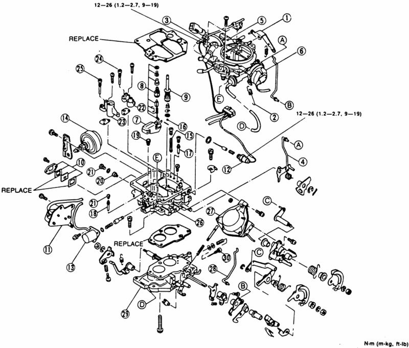
Fig. 1: B2200 exploded view of the carburetor, refer to the text for component identification-B2600 similar
After removing the carburetor, disassemble the carburetor in the numbered order (refer to the exploded view illustrated in this section) and also refer to the rebuid kit manufacturers instructions as follows:
1. Accelerator pump connecting rod.
2. Connect spring.
3. Air vent solenoid valve.
4. Choke rod.
5. Air horn.
6. Automatic choke assembly.
7. Float.
8. Needle valve assembly.
9. Accelerator pump.
10. Fuel bowl sight glass.
11. Idle switch.
12. Slow cut fuel solenoid valve.
13. Coasting richer solenoid valve.
14. Dashpot.
15. Accelerator pump outlet check ball.
16. Accelerator pump inlet check ball.
17. Primary slow jet.
18. Secondary main jet.
19. Primary main jet.
20. Secondary main jet.
21. Plug.
22. Primary venturi and nozzle.
23. Secondary venturi and nozzle.
24. Primary main air bleed.
25. Secondary main air bleed.
26. Main body.
27. Vacuum diaphragm.
28. Throttle link.
29. Throttle body.
30. Mixture adjusting screw.
Further detailed disassembly procedures for component units follow:
AIR HORN AND AUTOMATIC CHOKE DISASSEMBLY
1. Vacuum hose.
2. Accelerator pump connecting rod, spring and lever.
3. Connect spring.
4. Air vent solenoid valve (separate from connector).
5. Choke rod (disconnect).
6. Air horn and automatic choke (separate from the main body).
7. Air vent solenoid valve, spring and gasket, if necessary.
NEEDLE VALVE AND FLOAT
See Figure 2
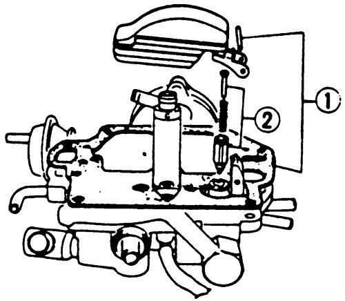
Fig. 2: Locations of the float pin and gasket (1), and needle valve assembly (2)
1. Float, pin and gasket.
2. Needle valve assembly.
3. Fuel bowl sight glass mounting screws.
4. Cover, gasket, glass and rubber gasket.
AIR BLEED AND JETS
See Figure 3
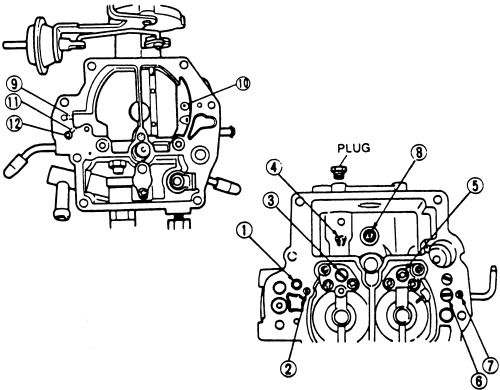
Fig. 3: Locations of the air bleeds and jets, refer to the text for identifications
1. Secondary slow jet.
2. Secondary slow air bleed (No.1).
3. Secondary main air bleed.
4. Secondary main jet.
5. Primary main air bleed.
6. Slow jet and plug.
7. Primary slow air bleed (No.1).
8. Primary main jet.
9. Richer air bleed (No.2).
10. Primary slow air bleed (No.2).
11. Richer air bleed (No.1).
12. Richer jet.
13. Note the size of all jets and air bleeds so that they are reassembled in the correct position.
MAIN BODY
1. Coasting richer solenoid valve and O ring.
2. Idle switch and spring. After installing the idle switch be sure to adjust it.
3. Slow cut solenoid valve, needle valve, spring and gasket.
4. Dashpot bracket and dashpot.
5. Accelerator pump plunger assembly and spring.
6. Retaining clip.
7. Strainer and accelerator pump inlet check ball.
8. Check valve plug.
9. Accelerator pump outlet check ball and spring.
10. Throttle link (disconnect).
11. Vacuum diaphragm connecting rod (disconnect).
12. Throttle return spring (disconnect).
13. Throttle body (separate from the main body). One of the bolts is inside the throttle body.
14. Diaphragm assembly and gasket.
15. Diaphragm cover mounting screws and cover.
16. Spring and diaphragm.
17. Throttle lever hanger mounting screws.
THROTTLE BODY
See Figure 4
When removing the mixture adjusting screw, tap out the spring pin as shown in the illustration provided in this section. Do not remove the throttle valve and shaft, the venturi, the choke valve and shaft.
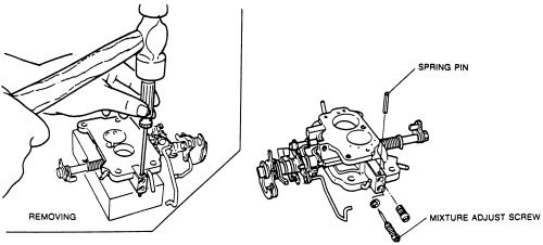
Fig. 4: Removal of the mixture control spring pin retainer in order to access the mixture adjusting screw
INSPECTION
Before inspection, wash all parts in carburetor cleaner and blow compressed air into the fuel passages to remove any dirt. Never use wire to clean the jets.
1. Inspect the air horn, the main body and the throttle body for cracks or breakage.
2. Inspect the choke shaft and throttle shaft for wear. A worn throttle shaft will allow air to enter the combustion chamber and the air/fuel mixture will become lean at low driving speeds.
3. Check the needle and seat for wear and rust. It is a good policy to always replace the needle and seat when cleaning/rebuilding the carburetor.
4. Check the float for damage.
5. Examine all jets and air bleeds for clogging and blow out with compressed air if necessary.
6. Inspect the accelerator pump plunger cup. Replace the plunger if it is worn or damaged. It is a good policy to replace the accelerator pump when cleaning or rebuilding the carburetor.
7. Check the diaphragm for damage.
8. Inspect the mixture adjuster for burrs or ridges.
9. Check the operation of the solenoids. To check, connect the solenoid terminal, with jumper wires, to the positive terminal of the battery and ground the solenoid body. When current is applied to the solenoid, the valve stem should be drawn into the valve body. If the valve does not operate properly, replace the solenoid.
10. Use and ohmmeter and check for continuity between the coupler and the choke heater ground. If there is no continuity, replace the choke heater.
11. To check the A/F solenoid valve, connect the terminal to the positive terminal of the battery, and ground the other terminal. Make sure the valve is operating properly by blowing air through it. When current is applied, no air should pass through. When no current is applied, air should pass through. The A/F solenoid cannot be replaced, if it is not operating properly, the air horn assembly must be replaced.
ASSEMBLY
Assemble the components by following the steps in reverse order. After components cleaned and assembled combine them. Always use new gaskets and O rings. Make sure all parts are in good condition and clean. Both the primary and secondary venturi have their respective components which are the same shape. During reassembly be careful not to mix up the parts. Do not install the mixture spring pin until the idle adjustment has been completed. Be sure to make a float level adjustment when assembling the carburetor.
Install the carburetor
1. Start the engine and check for leaks.
2. With the engine operating, check the fuel level. The fuel level should be at the specified mark on the sight glass.
3. Make the idle adjustment.
4. After the idle adjustment is made, press in the spring pin.
5. Adjust the dashpot. (see Driveability & Emissions Controls )
6. Adjust the idle switch.
7. After the idle adjustment is completed, check the fast idle speed as follows:
8. Start the engine and allow it to reach normal operating temperature.
9. Stop the engine and remove the air cleaner.
10. Plug the hoses to the idle compensator and the reed valves.
11. While holding the throttle valve slightly opened, push the choke to the fully close it, and then release the choke valve after releasing the throttle valve.
12. Start the engine, but do not touch the accelerator pedal.
13. Check to see that the engine speed increases to 2500-3000 rpm. If the engine speed is not as specified for fast idle, turn the fast idle screw until the correct rpm is obtained.
14. Connect the reed valve and idle compensator hoses. Install the air cleaner.
B2600 Carburetor
DISASSEMBLY
After removing the carburetor, disassemble the carburetor in the numbered order (refer to the exploded view illustrated in this section) and also refer to the rebuid kit manufacturers instructions as follows:
1. Water hose.
2. Throttle return spring.
3. Choke cover.
4. Throttle sensor.
5. Dashpot.
6. Jet mixture solenoid valve.
7. Enrichment solenoid valve.
8. Slow fuel cut solenoid valve.
9. Air vent solenoid valve.
10. Choke breaker.
11. Secondary diaphragm.
12. Choke rod.
13. Float chamber cover.
14. Float.
15. Needle valve.
16. Main jet.
17. Jet block.
18. Secondary slow jet.
19. Primary slow jet.
20. Jet mixture jet.
21. Outlet check weight and ball.
22. Inlet check ball.
23. Steel ball.
24. Accelerator pump.
25. Mixture adjustment screw.
INSPECTION
Clean all parts with carburetor cleaner and dry with compressed air. Check for the following, replace the part if a problem is found.
1. Damaged float chamber, mixing body, or throttle body.
2. Improper operation of the choke valve or throttle valve.
3. Damaged float.
4. Needle valve abrasion or improper seating.
5. Clogged or damaged jets or air bleeds.
6. Damaged diaphragm on the accelerator pump.
7. Weak or broken spring on the accelerator pump.
8. Damaged diaphragms.
9. Improper solenoid operation.
ASSEMBLY
The carburetor is equipped with a tamper proof choke. To remove the choke cover, grind off the heads of the choke cover lock screws. When installing the cover use new lock screws. After carburetor assembly (in reverse order of the above listed steps), float level adjustment and choke adjustment will be necessary.
1. To adjust the choke; with the cover removed, remove the two lock screws and remove the choke pinion assembly.
2. Fit the strangler spring to the choke lever. Assemble, aligning the inscribed line or black painted line on the tooth of the choke pinion with the inscribed line on the cam lever.
3. Loosely tighten the new lock screws. Set the choke valve by moving the pinion arm up or down, align the punch mark on the float chamber cover with the center of the three inscribed lines, secure the pinion arm with the lock screws.
Inspect the operation of the various solenoid valves. Apply battery power to the valve (positive battery terminal jumper to solenoid terminal and ground solenoid body with another jumper) and check for operational sound from each valve, replace as necessary. Install the carburetor and adjust the idle and fast idle speeds.
ADJUSTMENTS
Fast Idle
2.2L ENGINE
See Figure 5
1. Set the fast idle cam so that the fast idle lever rests on the second step of the cam.
2. Adjust the clearance between the air horn wall and the lower edge of the throttle plates, by turning the fast idle adjusting screw. Clearance should be 0.0331-0.0409 inch (0.84-1.04mm). Make sure that the choke valve clearance hasn't changed.
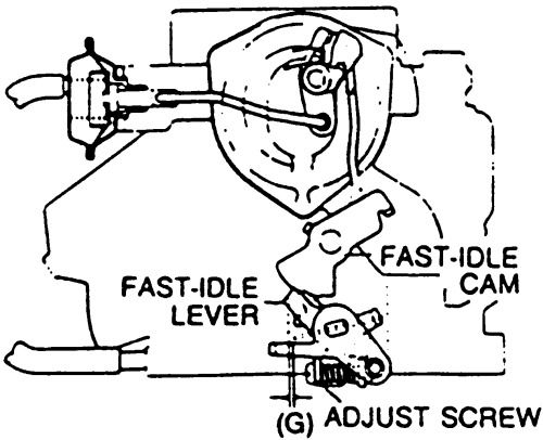
Fig. 5: Fast idle cam adjustment
2.6L ENGINE
Before making the adjustment, the carburetor should be at 73°F (23°C) for at least 1 hour.
1. With the carburetor off the engine, invert it and check the opening between the throttle plate and the air horn wall. The clearance should be 0.0279 inch (0.71mm) if equipped with manual transmission; 0.0315 inch (0.80mm) if equipped with automatic transmission.
2. If not, adjust the opening by turning the fast idle adjustment screw.
Idle Speed
Make sure the ignition timing, spark plugs, and carburetor float level are all in normal operating condition. Turn off all lights and other unnecessary electrical loads.
1. Connect a tachometer to the engine.
2. Start the engine and allow it to reach normal operating temperature. Make sure the choke valve has fully opened.
3. Check the idle speed. If necessary, adjust it to specification by turning the throttle adjusting screw. The idle speed should be 800-850 rpm with manual transmission in neutral or automatic transmission in P.
Idle Mixture
2.2L ENGINE
1. Start the engine and allow it to reach normal operating temperature. Let the engine run at idle.
2. Connect a dwellmeter (90°, 4-cylinder) to the air/fuel check connector (Br/Y).
3. Check the idle mixture at the specified idle speed. The idle mixture should be 20-70°. If the idle mixture is not as specified, adjust as follows:
a. Remove the carburetor and knock out the spring pin. Install the carburetor.
b. Install the air cleaner and make sure the idle compensator is closed. Make sure all vacuum hoses are properly connected.
c. Connect a tachometer to the engine.
d. Warm up the engine and run it at idle. Make sure the idle speed is correct.
e. Reconnect the dwell meter to the air/fuel check connector.
f. Adjust the idle mixture to 27-45° by turning the mixture adjust screw.
g. Tap in the spring pin.
2.6L ENGINE
1. Start the engine and allow it to reach normal operating temperature. Let the engine run at idle.
2. Connect a dwellmeter (90°, 4-cylinder) to the jet mixture solenoid valve connector (Y/G) wire. The check connector is located near the No. 3 ACV and reed valve case assembly.
3. Check the idle mixture at the specified idle speed. The idle mixture should be 27-45°. If the idle mixture is not as specified, check the oxygen sensor, feedback control unit and the wiring between the sensor and control unit.
4. If the oxygen sensor, feedback control unit and wiring are okay, adjust the idle mixture as follows:
a. Remove the carburetor and mount it in a vise with the mixture adjust screws facing up. Protect the gasket surface from the vise jaws.
b. Drill a 0.079 inch (2mm) pilot hole in the casting toward the mixture adjust screw, then redrill the hole to 0.118 inch (3mm).
c. Insert a blunt punch into the hole and drive out the antitamper plug. Reinstall the carburetor.
d. Connect a tachometer to the engine. Start the engine and allow it to reach normal operating temperature. Let the engine run at idle. Make sure the idle speed is correct.
e. Reconnect the dwell meter to the jet mixture solenoid valve connector. Adjust the idle mixture to 36° ± 9° by turning the mixture adjust screw.
f. Press in a new antitamper plug.
Float and Fuel Level
See Figures 6 and 7
1. Remove the air horn from the carburetor.
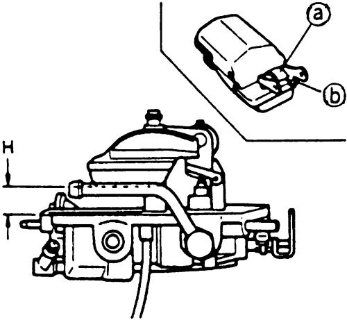
Fig. 6: Adjusting the float level with the air horn turned upside down
2. Turn the air horn upside down on a level surface. Allow the float to hang under its own weight.
3. Measure the clearance between the float and the air horn gasket surface. The gap should be 0.4567-0.4960 inch (11.6-12.6mm) for vehicles with manual transmission; 0.4212-0.4606 inch (10.7-11.7mm) for vehicles with automatic transmission. If not, bend the float seat lip to obtain the correct gap.
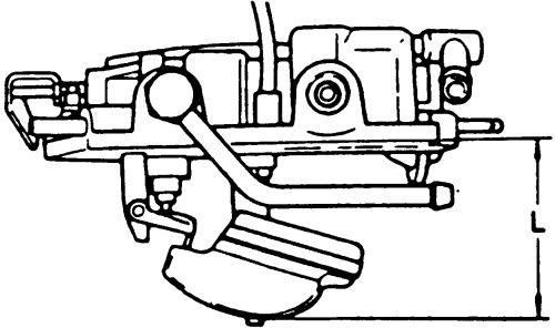
Fig. 7: Adjusting the float level with the air horn right side up and the float hanging under its own weight
4. Turn the air horn right side up and allow the float to hang under its own weight.
5. Measure the gap between the BOTTOM of the float and the air horn gasket surface. The gap should be 1.811-1.850 inch (46.0-47.0mm). If not, bend the float stopper until it is.
2.6L ENGINE
1. Remove air horn from carburetor main body.
2. Remove air horn gasket and invert air horn.
3. Using a gauge measure the distance from bottom of float to air horn surface. The distance should be 0.787 inch ± 0.0394 inch (20mm ± 1mm). If distance is not within specification, the shim under the needle and seat must be changed. A shim pack is available which has three shims: 0.008 inch (0.2mm), 0.012 inch (0.3mm), or 0.021 inch (0.5mm). Adding or removing one shim will change the float level three times its thickness.
Accelerator Linkage
1. Check the cable deflection at the carburetor. Deflection should be 0.0394-0.1181 inch (1.0-3.0mm) . If not, adjust it by turning the adjusting nut at the bracket near the carburetor.
2. Depress the accelerator pedal to the floor. The throttle plates should be vertical. If not, adjust their position by turning the adjusting nut on the accelerator pedal bracket.
Secondary Throttle Valve
See Figure 8
The clearance between the primary throttle valve and the air horn wall, when the secondary throttle valve just starts to open should be 0.2894-0.3249 inch (7.35-8.25mm). If not, bend the tab.
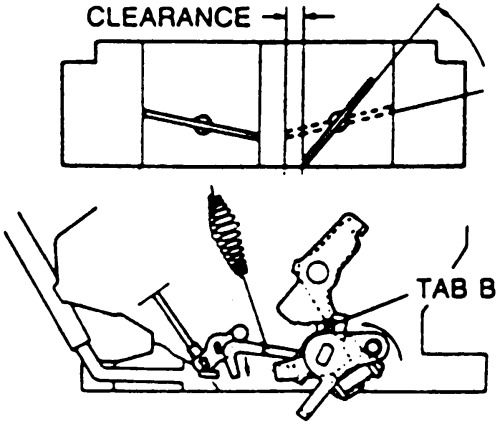
Fig. 8: Adjusting the secondary throttle valve clearance
Choke
2.2L ENGINE
Three choke related adjustments are performed on these units.
CHOKE DIAPHRAGM
See Figure 9
1. Disconnect the vacuum line from the choke diaphragm unit.
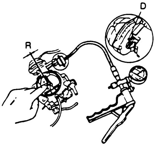
Fig. 9: Adjusting the choke diaphragm
2. Using a vacuum pump, apply 15.7 inch Hg to the diaphragm.
3. Using light finger pressure, close the choke valve. Check the clearance at the upper edge of the choke valve. Clearance should be 0.067-0.085 inch (1.70-2.16mm).
4. If not, bend the tab on the choke lever to adjust it.
CHOKE VALVE CLEARANCE
See Figure 10
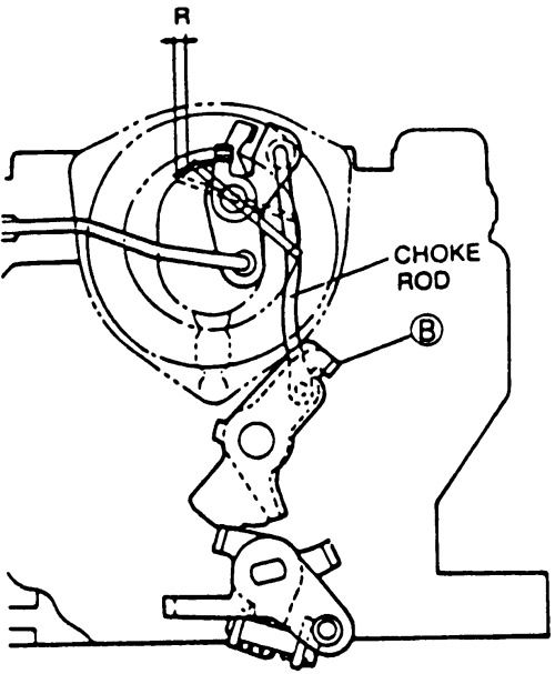
Fig. 10: Adjusting the choke valve clearance
1. Position the fast idle lever on the second step of the fast idle cam.
2. The leading edge of the choke valve should be 0.024-0.045 inch (0.60-1.14mm) from fully closed. If not, bend either the tab on the cam or the choke rod to adjust. The tab will give smaller adjustment increments.
CHOKE UNLOADER
See Figure 11
1. Open the primary throttle valve all the way and hold it in this position.
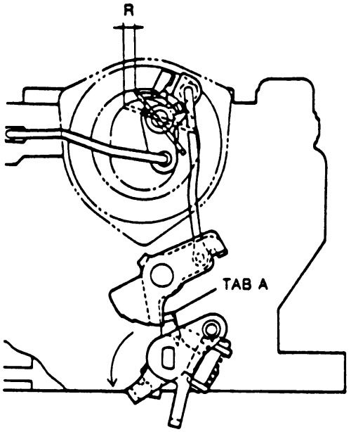
Fig. 11: Adjusting the choke unloader system
2. The leading edge of the choke valve should be 0.110-0.143 inch (2.80-3.62mm) from fully closed. If not, bend the tab on the throttle lever.
Idle Switch
1. The idle switch adjustment is not necessary unless it has been replaced or tampered with.
2. Start the engine and allow it to reach normal operating temperature. Stop the engine and connect a suitable tachometer.
3. Connect a voltmeter to the idle switch terminal (LgR).
4. Start the engine and increase the speed to above 2000 rpm and decelerate gradually.
5. Take a reading on the voltmeter. At idle, there should be approximately 12 volts and above 1000-1200 rpm it should be below 1.5 volts.
6. If the readings do not agree with these specifications, turn the adjusting screw to obtain the correct reading.
Credits
Created By: fantomrush
Related Articles
stock carb woes. experienced mechanics only.
so I'm waiting for my weber to arrive... it's taking too long... I've been fighting a bad stutter l...
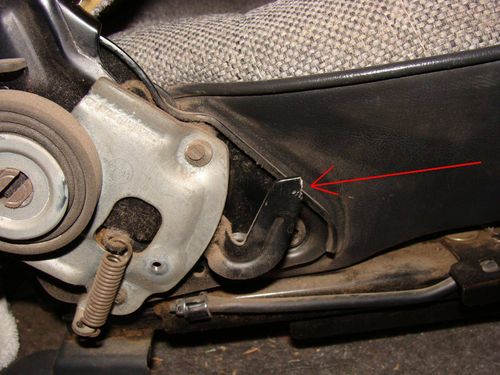
Bucket seat release handle repair
I had this happen on mine, and I fixed it Home Depot style. [pid]18249[/pid] I used an L-shaped m...

My October 2011 B2200 Engine Rebuild
My October 2011 B2200 Engine Rebuild, salvaged from my MazdaTrucking.com thread. At 182,900 miles, ...
How to install 01 & up Ranger Headlights
This is how I did the conversion on my truck and hopefully it helps. The tools I used were a cut o...